One of the most cherished effect used by MC68000 assembly coders on the Amiga has been the sine scroll, the scroll of some text deformed by changing the ordinate of its consecutive columns of pixels along a sine curve, as in this intro by Falon :

The best of its kind is the one-pixel sine scroll, where each column of pixels is displayed at a given ordinate. However, as it will be shown here, this kind of sine scroll requires too much CPU cycles when drawn only by the CPU. For performance improvement, we shall lighten the CPU workload by relying on two graphic coprocessors: the Blitter and the Copper.
This article may be read by anyone, having been written for those who have never coded in MC68000 assembly language, even less metal-bashed the hardware of the Amiga. It has been translated by the author from the french version, published in Programmez! #214-218 between 2017 and 2018. Sorry for the poor english: suggestions for improvements are welcome here.
Click here to download the archive of the source and data of the program hereby explained.
This archive contains several sources :
- sinescroll.s is the basic version which we will code until we decide to optimize it;
- sinescroll_final.s is the optimized version of the previously mentioned basic version;
- sinescroll_star.s is an enhanced version of the optimized version.
If you’re using Notepad++, click here to download and enhanced version of the UDL 68K Assembly (v3).
This article is the first of five. We shall learn how to install a development environment on Amiga emulated with WinUAE, and how to code a basic Copper list to display something on the screen.
NB : This article may be best read while listening to the great module composed by Nuke / Anarchy for the diskmag part of Stolen Data #7, but this is just a matter of personal taste…
Cliquez ici pour lire cet article en français.
06/16/2018 update: StingRay / Scoopex helped to correct misprints, adjust the vocabulary, add some details regarding comptability. Thanks, dude!
Installing a development environment
Note that the documentation that proved to be useful for coding the sine scroll is available online:
- The Amiga Hardware Reference Manual, which details the inner workings and the way to code the Amiga hardware;
- The M68000 Family Programmer’s User Manual, which details the instructions of the MC68000;
- The M68000 8-/16-/32-Bit Microprocessors User’s Manual, which details the time required to execute those instructions;
- The ASM-One manual, of which you shall find a more up-to-date version in AmigaGuide format in the archive of this tool (browsing on the Amiga only, though).
The same goes for the tools, starting with the Amiga emulator. No need to buy an Amiga on eBay for coding nowadays on this machine. We use the great emulator WinUAE, which we configure to emulate a hard disk from a folder on the PC. This way, we may write the code in a text editor running on Windows, then load the code for compilation and testing in ASM-One running on an A1200 emulated by WinUAE.
Once we have downloaded and installed WinUAE, we have to get our hands on the ROM and the operating system, meaning the Kickstart and the Workbench in their 3.1 versions. The Kickstart and the Workbench are copyrighted. You can buy them for a dozen bucks on Amiga Forever.
In WinUAE, let’s start by creating the configuration for emulating an Amiga 1200 in Hardware :
- in CPU and FPU, select a MC68020;
- in Chipset, select AGA;
- in ROM, select the Kickstart 3.1;
- in RAM, choose 2 Mb of Chip and no Slow at all;
- in CD & Hard drives, click on Add Directory or Achives… and add a device named DH0: matching a folder on the PC where the files stored on this hard disk emulation will be located.
The configuration having been created, let’s save it. For this purpose, click on Hardware, give it a name and click on Save. This way, we may reload the configuration at any time if required, by simply double-clicking it.
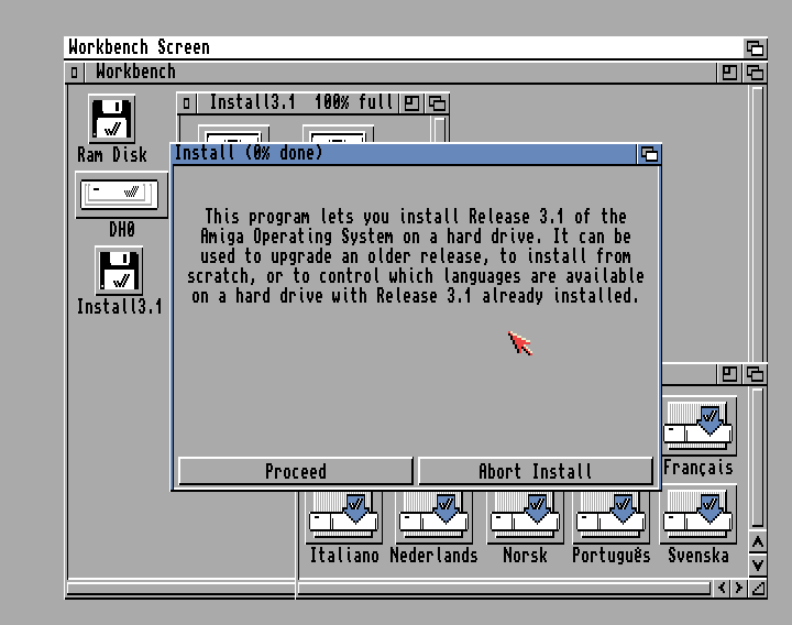
In the same section, go in Floppy Drives to emulate the insertion in the disk drive DF0: of the first disk of the Workbench – the one labeled Install 3.1. As long as we are there, let’s set the emulation speed of the disk drive to the maximum (slider set to left, on Turbo) to spare some time.
We may now click on Reset to start the emulation.
Once the Workbench has been loaded, it’s all about installing it on the hard disk so we do not have to wait for a long time before it’s done. Double-click on the icon of the disk Install 3.1, then on the icon of its Install folder, and eventually on the one of the version of the installation we want. Let’s go through the installation process of the Workbench on the hard disk:
Once the operating system has been installed on the hard disk, we have to install the development environment. We use ASM-One to compile the source and link it with the data to create an executable. As it goes for all the files, we just have to download the archive on the PC and drop its contents in a subfolder of the folder emulating the hard disk. Remember that in the Workbench, the only visible folders are those that come with a .info file. The quickest way is to create the folder in the Workbench – click on the right mouse button in the task bar on the top of the screen.
To use ASM-One, we must:
- Click here to download reqtools.library and copy this file in the Libs folder. ASM-One uses this library to display a dialog box that facilitates the browsing in the file system.
- Use a Shell command (which lies in the System folder) to assign SOURCES: to the folder that contains the code and the data (for example : assign SOURCES: DH0:sinescroll). To avoid repeating this every time we start the Amiga 1200 emulation, write this line in a file named User-Startup, which should be found in the S folder.
Once ASM-One is started, allocate a workspace in any memory area (Chip or Fast). 100Ko should fit. In the Assembler menu, select Processor then 68000. That’s because we are coding for the Amiga 500. Input the command R (Read) to load the source.
When it comes to compiling and testing, there are two solutions:
- If we want to debug, press the Amiga (right) + Shift (right) + D keys, the Amiga (right) key being emulated with the Windows (right) key. This runs the debugger, where you may execute the code line by line by pressing the downward direction key, or run the whole code by pressing the Amiga (right) + R keys.
- If we don’t want to debug, we may press the Amiga (right) + Shift (right) + A keys, or input the A (Assemble) command to compile the code, and then input the J (Jump) to run it.
We won’t have to use more ASM-One functionalities, if not for creating and executable file. That’s because ASM-One is not required to write the code: let’s use a text editor running on Windows that can save a text file ANSI encoded, as does the great Notepad++. Let’s just load the file in ASM-One to compile it and to run it whenever we want.
However, if we want to be able to write some code in ASM-One as well as in Notepad++, which may be useful, we have to disable the marks saving that adds special characters at the begining of the file. Select Project in ASM-One, then select Preferences and deselect Save marks.
If we want to speed up the loading of this development environment, we may press the F12 key once ASM-One is loaded and some workspace has been allocated in memory. In the WinUAE interface, click on Miscellaneous in Host, then on Save State… to save the state of the emulation. Starting from now, once WinUAE is started, we will just have to load the configuration for the Amiga 1200, then click on Load State… to restore the state of the emulation, and then click on OK to go back to the Amiga 1200 as we left it when the state was saved – we can even configure WinUAE so that the state is loaded with the configuration. Nice!
Discovering the MC68000 assembly language
The MC68000 has 8 data registers (D0 to D7) and as many address registers (A0 to A7, the last one holding the stack pointer). Its set of instructions is quite large, but we use only a few of them. Our unfortunate ignorance may conveniently be taken for simple good taste.
The MC68000 instructions may come in mutiple variants. Let’s not review every variant of the few instructions we use. Some examples should be enough for you to understand how this works:
| Instructions | Description |
| Stockage | |
| MOVE.W $1234,A0 | Store in A0 the 16 bits value lying at address $1234 |
| MOVE.W $1234,D0 | Same thing with D0 |
| MOVE.W #$1234,A0 | Store in A0 the 16 bits value $1234 |
| MOVE.W #$1234,A0 | Same with D0 |
| LEA $4,A0 | Store in A0 the 32 bits value $4 |
| LEA variable,A0 | Store in A0 the address of the byte lying at the label “variable” |
| LEA 31(A0),A1 | Store in A1 the result of adding 31 to the contents of A0 |
| LEA 31(A0,DO.W),A1 | Store in A1 the result of adding the 32bits value that A0 contains, the 16 bits value that D0 contains, and the the integer value 31 |
| MOVE.L variable,A0 | Store in A0 the 32 bits value lying at the label “variable” |
| MOVE.L variable,D0 | Same thing with D0 |
| CLR.W D0 | Store in D0 the 16 bits value 0 |
| MOVEQ #-7,D0 | Store in D0 the 8 bits value -7 extended on 32 bits |
| MOVE.W D0,D1 | Store in D1 the 16 bits value stored in D0 |
| MOVE.B (A0),D0 | Store in D0 the 8 bits value lying are the address stored in A0 |
| MOVE.L (A0)+,D0 | Store in D0 the 32 bits value lying at the address stored in A0, then add 4 to the value stored in A0 to point to the next 32 bits value |
| MOVE.B (A0,D0.W)+,D1 | Store in D1 the 32 bits value lying at the address being the addition of the address stored in A0 and the 16 bits value stored in D0, then add 1 to the value stored in A0 to point to the next 8 bits value |
| Jumps | |
| JMP destination | Jump to the instruction at the label “destination”, no return possible |
| BRA destination | Same as JMP (simply speaking) |
| BNE destination | Same as JMP, but only if the Z (zero) flag in the CPU internal conditions register is not set |
| BEQ destination | Same as JMP, but only if Z is set |
| BGE destination | Same as JMP, but only if Z or C (carry) is set |
| BLE destination | Same as JMP, but only if Z is set or C is not set |
| BGT destination | Same as JMP, but only if C is set |
| DBF D0,destination | Subtract 1 to the value stored in D0 and jump to the instruction at the label “destination” if the result is not -1 |
| JSR destination | Same as JMP, but with a way to return |
| RTS | Jump to the instruction after the last executed JSR |
| Calculations | |
| BTST #4,D0 | Check if bit 4 of the value stored in D0 is set |
| BCLR #6,D0 | Clear (set to 0) bit 6 of the value stored in D0 |
| LSL.W #1,D0 | Shif 1 bit to the left the 16 bits value stored in D0 (unsigned multiplication by 2^1=2) |
| LSR.B #4,D0 | Shift 4 bits to the left the 8 bits value stored in D0 (unsigned division by 2^4=16) |
| ASL.W #1,d0 | Same as LSL, but keeping the sign bit in place (signed multiplication by 2^1=2) |
| ASR.B #4,D0 | Same as LSR, but keeping the sign bit in place (signed division by 2^4=16) |
| SWAP D0 | Switch the most significant 16 bits value (bits 31 to 16) and the less significant 16 bits value (bits 15 to 0) stored in D0 |
| CMP.W D0,D1 | Compare the 16 bits value stored in D1 and the 16 bits value stored in D0 |
| ADDQ.W 2,D0 | Add the 3 bits value 2 to the 16 bits value stored in D0 |
| ADD.B D0,D1 | Add the 8 bits value stored in D0 to the value stored in D1 |
| SUB.L D0,D1 | Add 32 bits value stored in D0 to the value stored in D1 |
So it is possible to have an instruction work only on 8, 16 or 32 bits of data. When a register is mentionned as an operator, the data matches the less significant byte, or the less significant word, or the whole long value stored in the register. For example:
	move.l #$01234567,d0		;D0=$01234567
	moveq #-1,d1				;D1=$FFFFFFFF
	move.b d0,d1				;D1=$FFFFFF67
	move.w d1,d0				;D0=$0123FF67
The execution of an instruction updates the flags in the CPU internal conditions register. This is pretty much self-explanatory. For example:
	move.b value,d0		;D0=[value]
	beq _valueZero		;Jump to _valueZero if [value] is 0
	btst #2,d0			;Test bit 2 of [value]
	bne _bit2NotZero	;Jump to _bit2NotZero if the bit is 0
	;...
_valueZero:
	;...
_bit2NotZero:
	;...
We use just one optimization, that is speeding up the computations by using binary operations instead of multiplications or divisions. For example:
	move.l #157,d0		;D0=157
	move.l d0,d1		;D1=157
	lsl.w #5,d0		;D0=157*2^5 so D0=157*32
	lsl.w #3,d1		;D1=157*2^3 so D1=157*8
	add.w d0,d1		;D0=157*2^5+157*2^3 so D0=157*40
We use very few variables. We define them by the end of the code, like this:
value8:		DC.B $12
	EVEN					;EVEN because the address of value16 shall be even
value16:	DC.W $1234
value32:	DC.L $12345678
As mentioned here, EVEN tells ASM-One that it must add a byte padding between $12 and $1234 so that this last value lies at an even address. Why? Because the MC68000 can not read 16 or 32 bits values lying at odd addresses.
Say bye-bye to the OS
ASM-One can create an executable that runs in the context of the OS. However, our code is not going to rely on the OS. We are even going to get rid of the OS so that we get complete control over the hardware. We just will conserve the integrity of the OS by not writing without control into the memory. To do so, we are going to to tell the OS to allocate the blocks we require in memory, and we will tell it to free them in the end. Between those two moments, the OS will be shut down.
;Stack the registers

	movem.l d0-d7/a0-a6,-(sp)

;Allocate a block of Chip memory and set it to 0 for Copper list

	move.l #COPSIZE,d0
	move.l #$10002,d1
	movea.l $4,a6
	jsr -198(a6)
	move.l d0,copperlist

;Same thing for the bitplanes

	move.l #(DISPLAY_DX*DISPLAY_DY)>>3,d0
	move.l #$10002,d1
	movea.l $4,a6
	jsr -198(a6)
	move.l d0,bitplaneA

	move.l #(DISPLAY_DX*DISPLAY_DY)>>3,d0
	move.l #$10002,d1
	movea.l $4,a6
	jsr -198(a6)
	move.l d0,bitplaneB

	move.l #(DISPLAY_DX*DISPLAY_DY)>>3,d0
	move.l #$10002,d1
	movea.l $4,a6
	jsr -198(a6)
	move.l d0,bitplaneC

;Same thing for the font

	move.l #256<<5,d0
	move.l #$10002,d1
	movea.l $4,a6
	jsr -198(a6)
	move.l d0,font16

;Shut down the system

	movea.l $4,a6
	jsr -132(a6)
StingRay / Scoopex : "Make sure to call LoadView(0) followed by two WaitTOF() calls before disabling DMA/Interrupts etc. as this will allow your code to work from non-native (i.e. RTG) screens. It's quite annoying for users with graphics cards to disable their card just to run a demo. :)". So, be careful!
AllocMem() and Forbid() are the two functions of the Exec OS library we use. To call an Exec function, we must store the argument values it expects in some registers, then jump to the right offset of the table of vectors - a table full of JMP -, which address lies at $4. The function returns its results in a given set of registers. For example, AllocMem () returns the address of the allocated block in D0.
AllocMem() allow us to allocate a block in memory for the Copper list, for three bitplanes - we are going to set up a triple buffering -, and the font - we are going to create a 16x16 font from a 8x8 one. All those blocks will lie in the Chip memory, the only kind of memory that the Copper and Blitter may access to, as opposed to Fast memory.
It requires more than calling Forbid() to shut down the OS. Indeed, the OS may have installed or allowed to install some code that is executed when a hardware event occurs. For example, when the electron beam finishes to paint the screen, the hardware generates VERTB event. This event takes the shape of level 3 interruption of the CPU. The CPU stops and execute the code lying at the address that is stored at index 27 of its interrupt vector table - the interrupt vector 27 -, which is $6C:
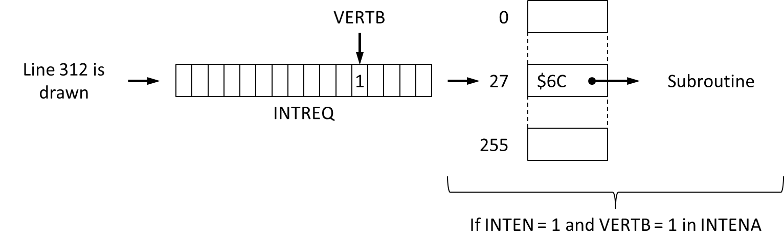
If our code were to use such hardware interrupts, we would have to divert the vectors, which means having them point to a RTE instruction:
;Diverts the interrupt vectors (code part). The hardware interrupts generate CPU interrupts of level 1 to 6 of du CPU associated to vectors 25 to 30 pointing to addresses $64 to $78

	REPT 6
	lea vectors,a1
	REPT 6
	move.l (a0),(a1)+
	move.l #_rte,(a0)+
	ENDR

;...

;Diverts the interrupt vectors (data part)

_rte:
	rte

vectors:	BLK.L 6		;To avoid allocating memory for 6 longs
This could be more brutal. We may have all the interrupt vectors for the CPU interrupts point to a RTE instruction. Indeed, the CPU interrupt vectors are not limited to those associated to hardware interrupts (from 0 to 7). There are 255 of them. For example, consider vector 5 - the code it points to is called whenever a division by 0 occurs. But diverting all those vectors should not be necessary.
StingRay / Scoopex : "68010+ CPU's allow to relocated the vector base using the VBR which means your code will not work correctly on such machines as soon as the VBR is relocated". So, be careful!
In this code, we don't use any interrupt. So, we just have to inhibit them. To do this, we must read in INTENAR to get the state of the activated interrupts, save this state, and inhibate the interrupts by writing in INTENA.
|
The hardware registers
This is the opportunity for talking about the way our code is going to talk with the hardware. We will use 16 bits registers lying at the address $DFF000 plus an even offset. For example, INTENAR lies at the address $DFF01C. We do as the manual tells us to avoid errors and make the code more readable. We store $DFF000 in some address register - that is A5 - and use offsets to make A5 point to the various hardware registers. For example:
INTENA=$09A
Each register is very specific. The meaning of each of its bits is described in the Amiga Hardware Reference Manual, a true manual, very well written by authors who had a deep understanding of the subject. The challenge for this article is not to copy what is told in this manual. You should stop reading this article at this point, read the appendice A of this manual to learn more about this register, then resume your reading.
|
It is also possible that some hardware interrupt requests may be pending. Indeed, whenever the hardware wants the CPU to be interrupted, and whether it has the possibility to interrupt the CPU or not, it indicates the reason for which it wishes to interrupt the CPU by setting bits in INTREQ - which forms with INTREQR one of those couples of registers such as INTENA and INTENAR seen before. If you ever want to use interrupts - which we won't use here, once again - you shall read the state of the pending requests in INTEQR and clear those requests by writing in INTREQ so that those interrupt requests are not mistaken for later ones.
A last register must be read: it's DMACONR. The coprocessors of the Amiga have direct access to the memory via the so-called DMA channels. Here again, it's something we want to have complete control over so that the only activated DMA channels are those we want to. We must read the state of the channels in DMACONR to get the state of the DMA channels, save this state, then close all the channels by writing in DMACON - to begin with, we close them all.
INTENA, INTREQ and DMACON run the same way: to inhibit an interupt, clear an interrupt request or close a DMA channel, we must write a word which bit 15 is set to 0 and which bit for the interrupt is set to 1.
All of that comes down to that. Write...:
- $7FFF in INTENA. We could have just disabled the INTEN bit, but if you want to use interrupts in the future, you won't want to have to write again in INTENA to disable those which you do not want to use before enabling INTEN and the interrupts you want to use.
- $7FFF in INTREQ. This register also contains a INTEN bit.
- $07FF in DMACON. What has been told about INTEN is true for the the DMAEN bit. We could have written $7FFF, we are lazy and bits 11 to 14 are not used.
;Shut down the hardware interrupts and the DMAs

	lea $dff000,a5
	move.w INTENAR(a5),intena
	move.w #$7FFF,INTENA(a5)
	move.w INTREQR(a5),intreq
	move.w #$7FFF,INTREQ(a5)
	move.w DMACONR(a5),dmacon
	move.w #$07FF,DMACON(a5)
Is it really clean? Certainly not. There's no clean way to shut down quickly the OS. That's why we talk about metal-bashing. Whatever, here we are: we have now full control over the hardware. Let's start by setting up the display.
Setting up the display
In a previous article (in french), I introduced the graphic coprocessors of the Amiga, among which the Copper, which controls the display. I explained that the Copper is programmed with a list of instructions, the Copper list. This has to be written in a sequence of long (32 bits) hexadecimal opcodes. The Copper understands three instructions (WAIT, MOVE and SKIP). At this time, we shall only use MOVE to tell the Copper that it has to write given values in given registers which control the display.
How does the display work? With bitplanes, planes of bits are overlayed so that reading a bit at coordinates (x, y) in the bitplane N gives the bit N-1 of the index of the color for the matching pixel in the palette, and so on. The number of colors depends of the number of bitplanes: N bitplanes mean 2^N colors. Here, we shall display one bitplane only, so two colors - background color included.
Let's define some constants to make the code readable:
DISPLAY_DEPTH=1
DISPLAY_DX=320
DISPLAY_DY=256
DISPLAY_X=$81
DISPLAY_Y=$2C
The following display parameters must be set:
- The resolution. The pixels are be displayed in low resolution. This is by default: it doesn't require setting any bit in any register.
- The number of bitplanes. The BPUx bits in BPLCON0 must code this number, which is DISPLAY_DEPTH.
- Displaying in colors. The COLOR bit in BPLCON0 must be set.
- The video surface to paint. DIWSTRT must contain the coordinates of its top left angle, while DIWSTOP must contain those of its lower right corner. Those coordinates are expressed in pixels in a very special coordinate system: the cathodic ray tube (CRT). Most of the times, the surface starts at ($81, $2C) and expands horizontally on DISPLAY_DX pixels and vertically on DISPLAY_DY pixels. Note that since the number of bits in DIWSTOP is limited, we must substract 256 from the coordinates before writing them in this register.
- The horizontal coordinates where the hardware has to start and stop reading the data for the pixels to display. Those abscissas are defined in the same coordinate system as those of the the angles of the video surface in DIWSTRT and DIWSTOP. The hardware reads the data of the pixels 16 pixels at a time. Moreover, the hardware requires some time to read the data before it displays the matching pixels. That's why as long as DISPLAY_DX is multiple of 16, the data reading must start at (DISPLAY_X-17)>>1.
|
Drawing pixels
What must be well understood is that once the resolution is set - low or high horizontal resolution, vertically interlaced or not - the rate if the electron beam is constant. The electron beam covers always the same surface of the CRT, displaying pixels by hitting with more or less power the red, green and blue parts of the luminophors on a given width (a sequence of luminophors form a pixel). The only thing the Amiga can do is to tell the electron beam to hit only the luminophors in a certain part of the screen, and hit those luminophors with more or less power.
DIWSTRT and DIWSTOP gives us control on the position and the dimensions of this surface. DDFSTRT and DDFSTOP gives us control on the positions where the Amiga starts and ends to read data from the bitplanes to retrieve the red, green and blue value for the electron beam hardware.
In other words, we shall not dream: it is not possible to display a whole line of a bitplane that would be smaller or bigger than the width of the screen and do the same thing vertically - a kind of video zoom. After the horizontal and vertical resolution are set with the bits in BPLCON0, they are frozen: whatever happens, the electron beam will take 140ns to draw a pixel and 1/50th of a second to draw the whole screen with a given width and a given height (the frame rate).
The Amiga interacts with a painter that paints always the same surface at the same speed. The only thing we may tell the painter to do at any time - as long as it is painting a pixel - is to modify what he takes from the red, green and blue color pots.
|
The remaining parameters must be disactivated. For example, we don't want to delay the display of odd bitplanes horizontally, and that's why we set the PF1Hx bits in BPLCON1 to 0. As another example, we don't want to display a high resolution screen, and that's why the HRES bit in BPLCON0 is also set to 0.
Which gives:
	move.w #DIWSTRT,(a0)+
	move.w #(DISPLAY_Y<<8)!DISPLAY_X,(a0)+
	move.w #DIWSTOP,(a0)+
	move.w #((DISPLAY_Y+DISPLAY_DY-256)<<8)!(DISPLAY_X+DISPLAY_DX-256),(a0)+
	move.w #BPLCON0,(a0)+
	move.w #(DISPLAY_DEPTH<<12)!$0200,(a0)+
	move.w #BPLCON1,(a0)+
	move.w #0,(a0)+
	move.w #BPLCON2,(a0)+
	move.w #0,(a0)+
	move.w #DDFSTRT,(a0)+
	move.w #((DISPLAY_X-17)>>1)&$00FC,(a0)+
	move.w #DDFSTOP,(a0)+
	move.w #((DISPLAY_X-17+(((DISPLAY_DX>>4)-1)<<4))>>1)&$00FC,(a0)+
The data for the pixels lie in a bitplane. We must tell where they lie in memory by writing their addresses in some couples of registers BPLxPTH (most significant 16 bits of the adddress) and BPLxPTL (less significant 16 bits of the address):
	move.l bitplaneA,d0
	move.w #BPL1PTL,(a0)+
	move.w d0,(a0)+
	swap d0
	move.w #BPL1PTH,(a0)+
	move.w d0,(a0)+
The hardware increments the addresses stored in BPLxPTH and BPLxPTL as it reads the data of the bitplane while drawing a line. Once the end of this line is reached, the hardware adds a given quantity of bytes to those registers so that they point to the first pixels of the next line: that value is called the modulo. BPL1MOD stores the modulo for the odd bitplanes, while BPL2MOD stores the value of the modulo for the even ones. BPL1MOD is the only required register at this time because one bitplane only is displayed. This is the bitplane 1, which is an odd bitplane. The modulo is set to 0, because this bitplane is DISPLAY_DX pixels wide and we want to display DISPLAY_DX pixels per line:
	move.w #BPL1MOD,(a0)+
	move.w #0,(a0)+
After it has retrieved the bits for the current pixel from the bitplanes, the hardware can guess the index of the color of the pixel in a palette. We set two colors in our palette by writing in COLOR00 and COLOR01 :
	move.w #COLOR00,(a0)+
	move.w #$0000,(a0)+
	move.w #COLOR01,(a0)+
	move.w #SCROLL_COLOR,(a0)+
The emulated Amiga is an Amiga 1200 with the AGA chipset, but the code we are writing must run on an Amiga 500 with the OCS chipset. Regarding the video, the ascendant compatibility of the AGA with the OCS is almost perfect. We just have to write 0 in FMODE :
	move.w #FMODE,(a0)+
	move.w #$0000,(a0)+
Eventually, the Copper detects the end of the Copper list when it finds an impossible WAIT instruction:
move.l #$FFFFFFFE,(a0)
We shall study how to write a WAIT later, when it is time to create a shadow and a mirror.
The Copper list having been created, we may tell the Copper to execute it. This requires two steps:
- store the Copper list address in COPL1LCH and COP1LCL, which may be done in one time with a MOVE.L (alike BPLxPTH et BPLxPTL, those registers are contiguous);
- write anything in the COPJMP1, which is just a strobe (a register which sole purpose is to trigger an action when its value is modified).
	move.l copperlist,COP1LCH(a5)
	clr.w COPJMP1(a5)
The Copper must still access to memory via DMA. That gives us the opportunity to reopen its DMA channel, and simultaneously the channel through which the hardware read the bitplanes data and the one through which the Blitter accesses memory:
move.w #$83C0,DMACON(a5) ;DMAEN=1, BPLEN=1, COPEN=1, BLTEN=1
The hardware is now configured. We can now work on the code that creates what will be displayed...